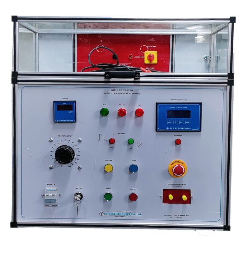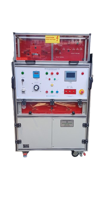
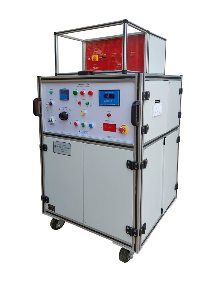
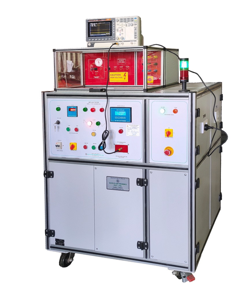
The SCR Elektroniks developed Impulse Voltage with Surge Current (Combination Waveform) is a high‑performance, PLC based high‑voltage test system engineered for surge immunity & impulse testing in accordance with IEC 61000-4-5 and other relevant standards designed to meet the demanding needs of modern electrical and electronic product validation.
The system generates 1.2/50 μs voltage impulse waveforms to evaluate insulation stress due to short‑duration voltage surges and 8/20 μs surge current waveforms, along with a CDN, to assess the surge immunity of electrical and electronic equipment.
Test sequences are fully programmable and easy to control. Users can adjust the peak voltage, select the polarity, number of impulses, and time intervals to enable precise, repeatable testing.
a) Verification of impulse voltage (1.2/50 μs) applied across clearances and solid insulation
b) Measurement of peak current across close contacts under surge conditions
c) Surge current tests using an 8/20 μs waveform with 2 Ω impedance
When used with a single‑phase Coupling and Decoupling Network (CDN), the impulse tester works together with the surge generator to safely apply surge impulses to the equipment under test (EUT).
The CDN enables proper surge coupling while isolating the mains supply and protecting auxiliary equipment, in line with IEC 61000‑4‑5 test requirements. It is rated for single‑phase operation at 240 V AC and 6 A, ensuring correct surge waveform application, electrical safety, and consistent, repeatable test results.
With the provision to connect an oscilloscope for waveform monitoring, the impulse tester forms a complete, accurate, and IEC‑compliant surge immunity test setup.

This system combines two essential test functions into a single, fully integrated platform:
The system is widely used by energy meter manufacturers, communication equipment manufacturers, information and communication technology (ICT) equipment manufacturers, and protection device manufacturers, including Residual Current Circuit Breakers (RCCBs) and Residual Current Breakers with Overcurrent Protection (RCBOs) therefore an ideal solution for R&D laboratories, routine production testing, and type testing, ensuring compliance with IEC and EN standards.
For surge current testing, in accordance with IEC 61000‑4‑5, a controlled combination surge characterized by 1.2/50 μs open‑circuit voltage and 8/20 μs short‑circuit current waveforms is applied via a CDN. This verifies the effectiveness of the equipment’s input surge protection circuitry under simulated lightning and switching transient conditions.
Principle Operation of the Test:
The test involves applying a specified high voltage between line–neutral and earth of the equipment under test (EUT). This checks the ability of the equipment to withstand short‑duration voltage surges caused by lightning and power system overvoltage.
The surge test is performed using an 8/20 µs surge waveform at the rated voltage under online conditions. The impulse (combination waveform) tester works by generating standard surge impulses to simulate real surge conditions and verify the surge withstand capability of the equipment.
Test Sequence:
| Standard | Title |
| IEC 61000 – 4 – 5 | Electromagnetic Compatibility – Testing and Measurement Techniques – Surge Immunity Test |
| IEC 60065 | Audio, video and similar electronic Apparatus |
| IEC 60335 | Functional safety standard for electrical appliances for and similar purposes. |
| IEC 60947 – 1 | Low Voltage Switchgear and Controlgear |
| IS 13252-1 / IEC 60950 – 1 | Information Technology Equipment – Safety |
| UL 60950 – 1 | Information Technology Equipment – Safety |
| BS 61180 | High Voltage Test Techniques for Low Voltage Equipment |
SCR ELEKTRONIKS Impulse Tester with Surge (Combination Waveform) is designed to carry out surge tests in accordance with IEC 61000‑4‑5. The system generates 1.2/50 μs voltage impulse waveforms to evaluate insulation stress due to short‑duration voltage surges and 8/20 μs surge current waveforms, along with a CDN, to assess the surge immunity of electrical and electronic equipment.